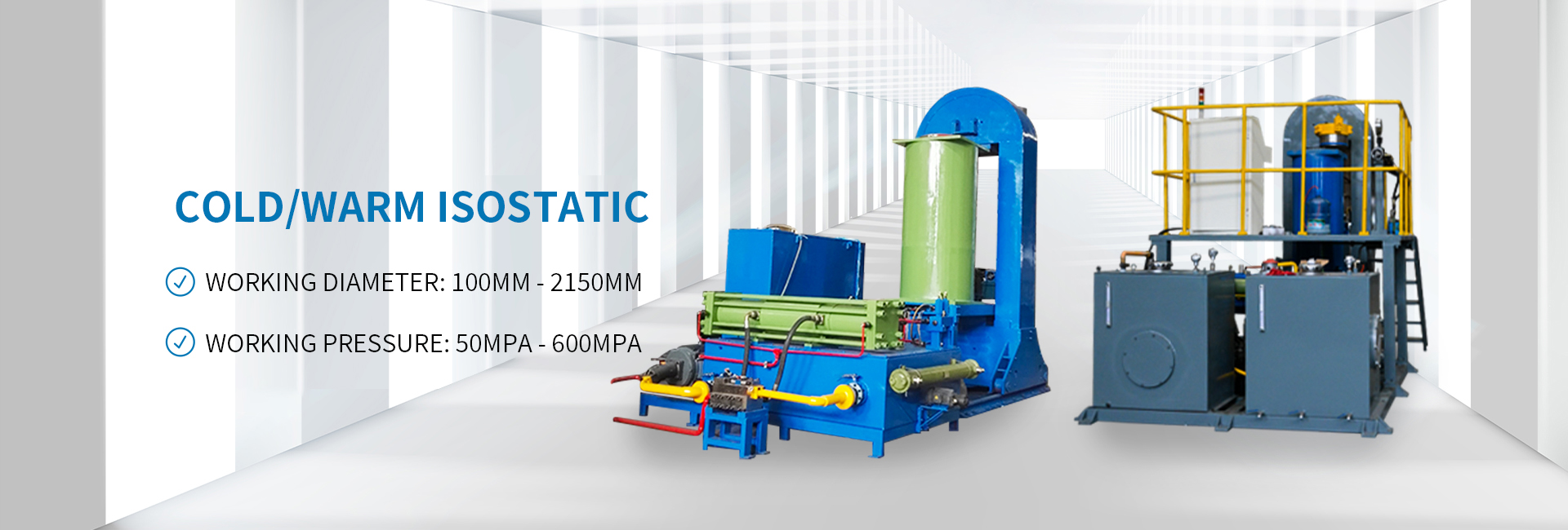
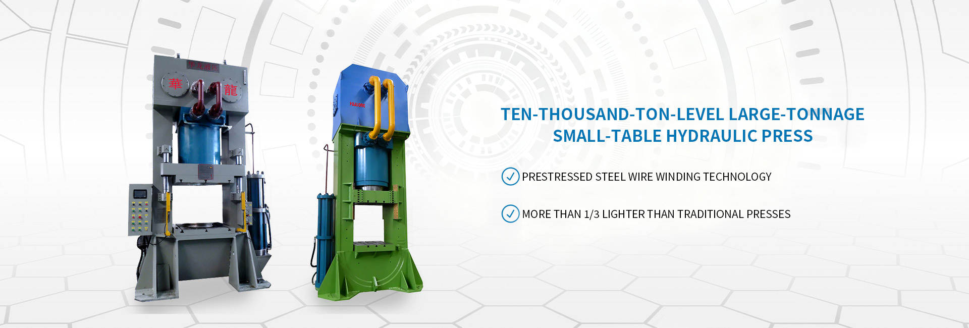
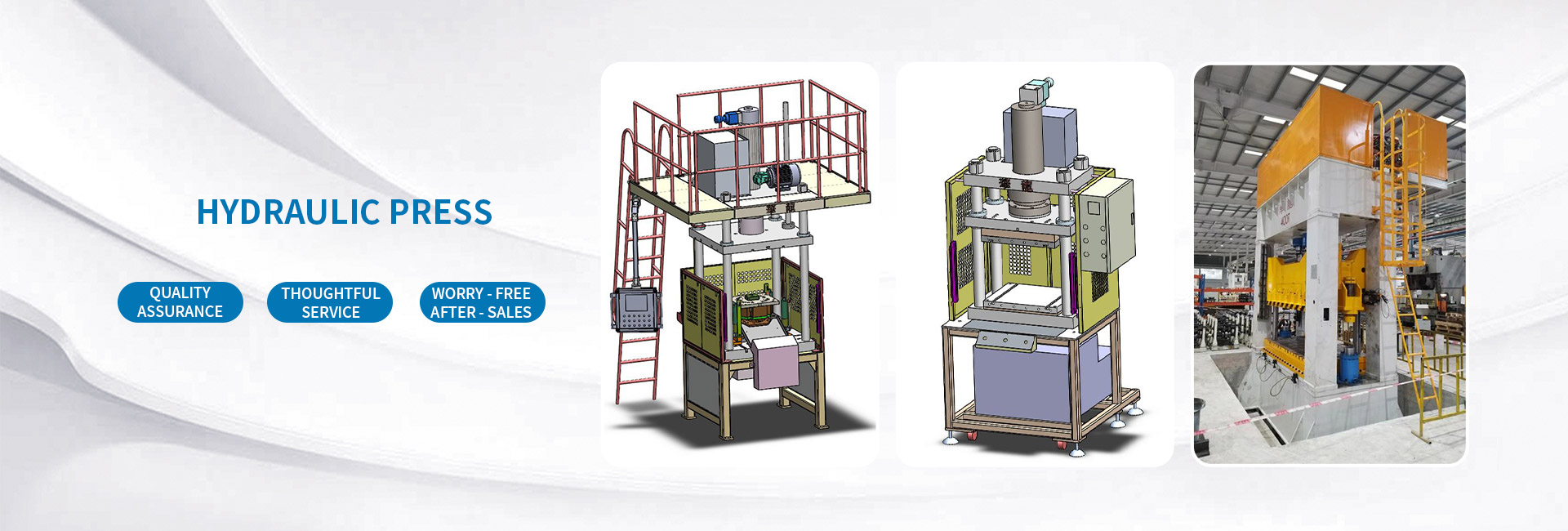
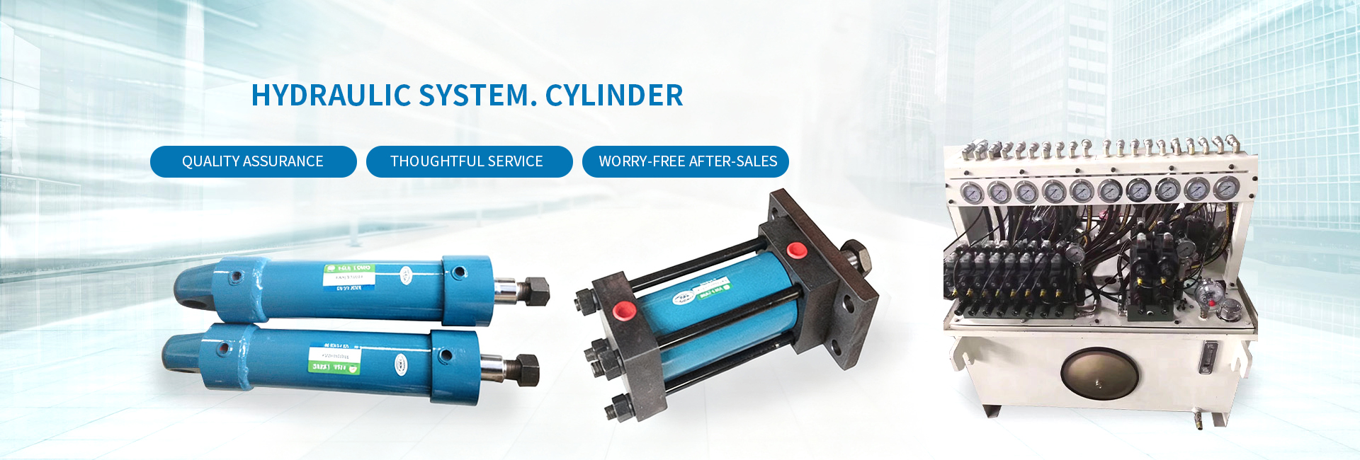
Xinhua Long Hydraulic
Focusing on research and development, production, and sales in the field of liquid industry
Contact person: Miss Wu
| Maintenance and Troubleshooting of Hydraulic System Machines | ||
| 1. Pump | ||
| Fault | Reason | Disposal |
| A No oil discharged | 1. Wrong rotation direction | Stop immediately and correct the rotation direction of the motor. If it continues to rotate, it will be the cause of burnout and damage. |
| 2. The pump is not rotating. | Repair the shaft coupling. | |
| 3. The pump shaft broke and the rotor did not rotate | Repair the pump, confirm whether the rotational speed and pressure are above the specified limits, and ensure that the shaft centers are aligned. | |
| 4. The suction pipe is clogged. | Check the suction pipeline. | |
| 5. The filter capacity of the fuel tank is insufficient | Clean the filter | |
| 6. The capacity of the fuel tank filter is insufficient | For larger capacity replacements, it should be more than twice the pump capacity. | |
| 7. The viscosity of the oil is too high | Change the oil type and set up the heater. | |
| 8. Insufficient rotation speed | Driven by the specified rotational speed. | |
| 9. Poor air tightness of the suction pipe | Check the suction pipeline. | |
| 10. The fuel tank filter is above the oil surface | Add oil to the reference line of the level gauge. | |
| 11. The blades slide out of the rotor trough | Repair the pump. | |
| B Loud noise | 1. The suction pipe is small and clogged | The suction vacuum degree should be below 200 MHZ. |
| 2. The fuel tank filter is clogged. | Clean the filter | |
| 3. The capacity of the fuel tank filter is insufficient | Use a filter with more than twice the capacity of the pump. | |
| 4. The viscosity of the oil is too high | Change the oil type and set up the heater. | |
| 5. When operating the double pump, the suction pipe is incorrect | Oil the suction pipe, identify the defective parts and repair them. | |
| 6. Air is drawn in through the suction pipe | Check whether the shaft centers are aligned. | |
| 7. Air is drawn in from the oil seal of the pump | Check the return oil pipe configuration. | |
| 8. There are bubbles in the fuel tank. | Add oil to the reference oil level. For the double-pump, different oil tanks must not be used separately. | |
| 9. The oil level is too low | Repair the pump. | |
| 10. The wheel blades cannot slide out of the blade grooves | Replace the damaged coupling with a new one, and reassemble the misaligned shaft center. | |
| 11. The postal coupling is making abnormal noises | Clean the vent holes or replace them. | |
| 12. The vent hole of the fuel tank is clogged or has insufficient capacity | Check the rotational speed. | |
| 13. The number of revolutions exceeded the specified limit | Check the pressure gauge. | |
| 14. Exceeded the specified pressure | Repair the pump and confirm whether the shaft centers are aligned. | |
| 15. Bearing wear | Abnormal wear is caused by dirty oil, water mixed in the oil, abnormal viscosity of the oil, or excessively high oil temperature during use. | |
| 16. Wear of CAM rings | Reassemble the pump and tighten it correctly with a torque wrench. | |
| 17. The pump cover is not tightened properly | Replace the pump. | |
| 18. The pump is damaged. | ||
| C Insufficient oil quantity | 1. No oil discharged | Refer to item (A) |
| 2. Excessive suction vacuum causes cavitation due to the intake of air (cavitation) | Check the suction oil filter and its configuration (try to use a hose or straight pipe). | |
| 3. The rotor cartridge is worn out and has a large amount of oil leakage inside | Repair the pump. | |
| 4. The oil pump cover is not tightened properly | Tighten correctly with a torque wrench. | |
| 5. The oil viscosity is too low | Change the oil type and install a cooler. | |
| D Sealing ring | 1. Sealing ring | Replace the shaft seal |
| There is oil leakage. | 2. There is a lot of internal oil leakage. | Repair the pump and check the viscosity of the oil |
| 2. Relief Valve | ||
| A The pressure is too high or too low | 1. Improper pressure setting | Reset the correct settings. |
| 2. Stress disorder | Verify the pressure gauge. | |
| 3. The lift valve is not correct on the seat surface | Take out the lift valve, reassemble or replace it, remove the adjusting bolt, and gently tap the lift valve several times from the outside with a guide rod. There is also a possibility of repair. | |
| 4. The balance piston is not functioning properly | Remove the upper cover to check the valve core hole (orifice) for any dust or other debris blocking it. | |
| 5. The force of the spring is too weak | Replace the spring. | |
| 6. The valve seat of the lift valve is worn out or there is dust on the balance piston seat | Clean or update. | |
| B Unstable pressure | 1. The balance piston is not functioning properly | Check whether there is dust in the valve core hole (orifice), whether the valve core operates smoothly, and the condition of the spring. |
| 2. The lift valve is unstable | Pressing the guide tip up and down several times can usually fix it. | |
| 3. Abnormal wear of the lift valve | Replace the lift valve and check if the oil is dirty. | |
| 4. There is air in the oil | Expel the air. | |
| 5. There is dust on the lifting valve seat | For details, see item (10), hydraulic oil contamination. | |
| C Slight pressure vibration (emitting abnormal sounds when severe) | 1. Abnormal wear of the lift valve | Replace the lift valve, check the degree of hydraulic oil contamination. |
| 2. Air from the oil drain port | Expel the air. | |
| 3. Resonance with other control valves | For details, see item (6), resonance, vibration and noise. | |
| 4. The piping of the fuel tank is poor | Re-piping. | |
| 5. Too high flow rate | Replace the larger control valve. | |
| 6. There is back pressure at the outlet | Use the balanced piston type. | |
| 3. Pressure Reducing Valve | ||
| Fault | Reason | Disposal |
| A The pressure is too high or too low | The same as the relief valve in item (2) | The same as the relief valve in item (2) |
| B Unstable pressure | 1. The valve core is not operating properly | The small hole (orifice) in the center of the valve core is blocked. Check the oil discharge volume. |
| 2. The lift valve is not safe | For details, see item (2) overflow. | |
| 3. Abnormal wear of the lift valve | For details, see item (2) overflow. | |
| 4. Air is mixed in the oil | Expel the air. | |
| 5. The variation of back pressure during oil drainage | It should be separated from the oil discharge pipes of other control valves, especially for hydraulic control valves. | |
| 4. Flow Control Valve | ||
| A The pressure correction device does not operate | 1. Dust adheres to the valve core | Disassemble and clean. |
| 2. Dust adheres to the small holes inside the sleeve | Disassemble and clean. | |
| 3. The pressure difference between the oil inlet and outlet is small | Minimum 10kgf/c㎡ | |
| B The rotation of the flow adjustment shaft is tight | 1. Dust adheres to the adjustment shaft | Disassemble and clean. |
| 2. It is used in the measurement input method when the secondary pressure is high | Adjust after reducing the pressure. | |
| 3. Below the starting point, the pressure is raised in one go | Rotate after reducing the pressure. | |
| 5. Direction Control | ||
| A The oil seal of the valve stem operated manually is leaking oil | 1. The oil seal is damaged | Replace the oil seal. |
| 2. There is back pressure at the oil drain port | Back pressure must be present 0.4kgf/c㎡ | |
| B The valve core of the mechanical operation cannot move | 1. There is back pressure at the oil drain port | Same as above. |
| 2. The angle of the cam that presses the valve core is too large | The cam angle should be below 30 degrees Celsius. | |
| 3. The piping of the pressure port and drain port is wrong | Correct the piping | |
| C The coil of the solenoid valve was burned out | 1. Poor insulation of the coil | Replace the electromagnetic coil. |
| 2. The core of the magnetic coil is stuck | Replace the core of the electromagnetic coil. | |
| 3. The voltage is too high or too low | Check the appropriate voltage adjustment. | |
| 4. The conversion pressure is above the specified limit | Lower the pressure and check the pressure gauge. | |
| 5. The conversion flow is above the specified limit | Replace the flow control valve. | |
| 6. There is back pressure at the return oil interface | For low pressure, it should be below 1.0kgf/c㎡; for high pressure, below 7.0kgf/c㎡. The return oil port should be directly connected back to the oil tank, especially for leakage (using external leakage). | |
| D The pilot-operated valve does not actuate | 1. Insufficient pilot pressure | The pilot pressure should be above 3.5kgf/c㎡. For full-open or mid-position drain valves, a check valve should be installed to form it. |
| 2. The valve core is stuck, disassemble, clean and wash | Pilot pressure. | |
| 3. Dust has entered, disassemble, clean and wash | Disassemble, clean and wash | |
| 6. Resonance, Vibration and Noise | ||
| A Spring and spring resonance | Resonance between springs of two or more control valves. (e.g., relief valve and relief valve, relief valve and sequence valve, relief and check valve). | 1. Offset the spring setting pressures by more than 10% or 10kgf/c㎡. |
| 2. Change the sensitivity of one spring. | ||
| 3. Use a remote control relief valve. | ||
| B Spring and piping resonance | Resonance between the spring of the control valve and the piping. (e.g., relief valve with long drain piping, resonance between internal pressure piping and piping). | 1. Change the spring sensitivity. |
| 2. Change the length, size, and material of the piping. (The sound changes when held by hand). | ||
| 3. Use appropriate supports to prevent piping vibration. (The sound stops when held by hand). | ||
| C Spring and air resonance | Resonance between the spring of the control valve and air. (e.g., air in the relief valve port, check valve port, etc.). | Completely expel the air from the oil circuit. |
| D Hydraulic cylinder vibration | Vibration of the hydraulic cylinder due to air. | Expel the air. Especially when oiling from only one side, the sealing ring of the oil seal must be sufficiently oiled or coated with copper sulfide grease. |
| E Oil flow sound | Oil flow noise, oil tank, piping vibration. Such as | 1. Replace the drain piping. |
| (1) The sound of oil from the relief valve oil tank interface hitting the oil tank. | 2. Use hoses for the piping as much as possible. | |
| (2) The sound at the L-shaped adjustment valve oil tank interface. | 3. Only merge after the flow has stabilized. | |
| (3) The sound when two pumps merge near their discharge sides. | ||
| F Oil tank resonance | Resonant sound of the oil tank | 1. Use thicker steel plate for the oil tank top plate. |
| 2. Lay another steel plate or rubber between the top plate and the pump, motor. | ||
| 3. Do not install the pump and motor on top of the oil tank, but connect them separately with rubber hoses. | ||
| G Valve switching sound | Switching sound of the spool valve | 1. Reduce the pilot pressure. |
| 2. Add a throttle valve | ||
| H Piping impact sound | Piping impact sound due to sudden pressure changes when the control valve switches | Replace the control valve or piping, reduce the sudden pressure change, use special plungers. Such as the oil circuit (decompression circuit) of an open full-oil valve. |
| I Pilot check valve hammering sound | Hammering sound when back pressure occurs on the secondary side of the pilot check valve | 1. Eliminate the back pressure on the secondary side. |
| 2. Increase the pilot pressure. | ||
| 3. Use an externally drained pilot check valve. | ||
| 7. Insufficient flow, insufficient pressure | ||
| 1 | The pump has no discharge | See item (1) A. |
| 2 | The pump sucks in air, high suction vacuum, cavitation occurs | See item (1) C. |
| 3 | Large internal leakage in the pump | See item (1) B. |
| 4 | The set pressure of the relief valve and pressure reducing valve is too low | See item (2) A. |
| 5 | The relief valve is in the open state (the control valve of the externally piloted port is in the open state) | The externally piloted port must be closed for the pressure to rise. |
| 6 | Hydraulic oil returns to the tank through the control valve in the oil circuit. For example, a directional control valve of the full-open or mid-position type in the neutral position | Check the movement of each control valve. |
| 7 | Internal leakage of control valves, hydraulic cylinders, etc. | 1. Check the individual leakage of each component. |
| 8 | External leakage of control valves, hydraulic cylinders, hydraulic motors, piping, etc. | 2. Check the viscosity and temperature of the oil. |
| 9 | Poor setting of the flow control valve | All external leakage except for the return oil piping must be completely avoided. |
| 10 | Setting change of the flow control valve | Must be locked tightly. |
| 11 | Poor operation of the flow control valve | See item (4). |
| 12 | The load is lighter than planned, or the friction resistance is reduced due to continuous operation | Reduce the setting of the pressure control valve (not due to a fault) |
| 13 | Viscosity change of oil passing through the flow control valve | Use a temperature-compensated control valve. |
| 8. Irregular movement of hydraulic cylinders, hydraulic motors, etc. | ||
| 1 | Air mixed in the oil circuit | See item (10) A. |
| 2 | The piston seal and piston rod seal are too tight | Install a vent at the highest point in the oil circuit and completely expel the air. |
| 3 | The center of the piston seal and piston rod seal is misaligned | More pronounced at low speeds, the tightness of the seal should be reduced. |
| 4 | Defects inside the hydraulic cylinder, inconsistent inner diameter, sticking due to dust | Measure the friction resistance of the hydraulic cylinder under no load and align the center. |
| 5 | The sliding surface of the guide plate is too tight, stuck, or poorly lubricated | Remove the hydraulic cylinder and check item by item. |
| 6 | Heavy load and slow movement | Forced lubrication, reduce the sliding area. |
| 7 | Poor operation of the flow control valve due to dust accumulation | See item (4) |
| 8 | Resonance of pressure control valve, flow control valve, etc., causing pulsating flow | See item (6) |
| 9 | Large leakage in hydraulic cylinder and hydraulic motor | Reduce overflow, increase pump displacement. |
| 10 | The setting of the sequence valve is close to that of the relief valve | Increase the setting of the relief valve by 10-15kgf/c㎡ or more than 10%. |
| 9. Significant rise in oil temperature | ||
| 1 | The pressure of the pressure control valve is too high | Should not be set too high, exceeding the necessary maximum operating pressure for full flow by more than 10kgf/c㎡. |
| 2 | High pressure and large capacity are discharged through the pressure control valve | Check the unloading oil circuit. |
| 3 | Internal leakage is too large due to low viscosity or pump failure | Repair the pump, replace the hydraulic oil. |
| 4 | Insufficient oil quantity in the oil tank | Add hydraulic oil, increase the tank capacity, review the position of the return oil pipe and filter, install a cooler, change the position of the baffle plate. |
| 10. Causes and Disposal of Hydraulic Oil Contamination | ||
| A Air (When air is mixed into the oil, it appears milky white; hydraulic oil must always be kept clear) | ||
| 1 | Pipe joints (suction side and discharge side) | During pump operation, apply oil to the piping to identify faulty areas. |
| 2 | From the shaft seal of the pump | Replace the oil seal. |
| 3 | From the gasket on the pump cover side | If the suction pressure is too low, it is more likely to suck in air, so the suction pressure should be kept above 200mmHg. |
| 4 | From the piston rod oil seal of the hydraulic cylinder | Replace the oil seal. |
| 5 | From the gasket of the hydraulic cylinder cover | Replace the gasket. |
| 6 | From the air bag of the accumulator | Replace the air bag. |
| 7 | From the gaskets of various components (elements) | Sometimes all components must be submerged below the oil level, and a check valve should be installed. |
| 8 | The oil level in the oil tank is too low | Add oil above the reference line of the oil level gauge. |
| 9 | The return oil tank is above the oil level, and oil is sprayed above the oil surface | Extend the piping below the oil level. |
| 10 | No baffle plate, sucking in bubbles from the oil tank | Use a baffle plate to separate the discharge side and suction side, allowing generated bubbles to float up and not be sucked in. |
| 11 | Poor hydraulic oil | Use hydraulic oil with excellent anti-foaming properties. |
| 11.B Water (When water is mixed into the oil, the oil appears milky white; hydraulic oil must always be kept clear) | ||
| 1 | From the breather hole of the oil tank | In humid areas, drain oil from the drain port every month to check for moisture in the oil; if the oil appears milky white, it must be replaced. |
| 2 | From the piping of the oil cooler | Repair the cooler piping. |
| 3 | On the oil tank cover | The oil tank must be airtight except for the breather hole. |
| 12.C Solids | ||
| 1 | Chips during assembly | Thoroughly flush. |
| 2 | Oil seals during piping | Pay attention to the installation method of the oil seals. |
| 3 | From the oil tank cover | The oil tank must be airtight except for the breather hole. |
| 4 | From the breather hole (filling port) of the oil tank | Install steel wool on the breather hole (filling port). |
| 5 | Wear of pump and control valve, etc. | Install a magnetic plug. |
| 6 | Paint on the inner surface of the oil tank | Use paint resistant to hydraulic oil. |
| 13.D Rubber adhesives | ||
| 1 | Gaskets dissolved by hydraulic oil | Use gaskets resistant to hydraulic oil; pay attention to the air bag of the accumulator as well. |
| 2 | Paint inside the oil tank | See item (C). |
| 3 | Oil seals of piping | Same as above. |
| 4 | Oil deterioration | Oil temperature should be controlled below 60℃, see item (9). |
| 4 | Oil deterioration | Use hydraulic oil with good antioxidant properties. |
| 14. Solenoid Valve | ||
| Poor operation | 1. The spool cannot return to its original position due to poor spring condition | Replace the spring |
| 2. Poor operation and sluggishness of the valve core | 1. Wash the inside of the control valve to remove contaminants from the oil. | |
| 2. Check the filter, wash the filter or replace the hydraulic oil if necessary. | ||
| 3. Check the wear of the spool, replace if necessary. | ||
| 3. Bolts are over-tightened or the body deforms due to temperature rise | Loosen the bolt tightness (tighten diagonally and alternately) | |
| 4. Abnormal wear of the valve core | Check the contact condition of the inserted terminals, confirm whether the electromagnetic coil is operating normally, replace if the coil is broken or burned out. | |
| Internal oil leakage | 1. Port seal ring damage | Replace. |
| External oil leakage | 2. Loose bolt | Tighten it up again. |
| Magnetic feld lines | 1. Load voltage error | Check the voltage and use the appropriate electromagnetic coil. |
| Circle noise | 2. Impurities such as dust enter | Remove impurities. |
| And bum damage | 3. The electromagnetic coil is damaged or burned out | Replace. |
| 4. Abnormal wear of the valve core | Replace. | |
| Countermeasures for hydraulic oil maintenance and management | |||
| 1.The operating temperature should be below 70℃, and if possible, it is best to keep it below 60℃. Especially when the working oil flowing back from the relief valve under high pressure is very high, or when using a heater for local heating, etc., great attention must be paid, as using at high temperatures will accelerate oxidation. | |||
| 2.To control pollution, the contaminants in the working oil sometimes act as catalysts, accelerating oxidation. | |||
| 3.Avoid water from mixing into the working oil, as water can deteriorate the working oil and too much water can cause it to emulsify. | |||
| 4.Working oils from different manufacturers must not be mixed. Also, working oils produced by the same manufacturer but with different names and grades should be avoided from being mixed. It may cause the deterioration of additives in the oil. | |||
| 5.To control the oil leakage of the hydraulic machine and piping, the leakage volume should be minimized. | |||
| 6.Regular inspection of working oil. | |||
| ※For working oil that has already begun to deteriorate, replenishing it with new oil cannot extend its service life; it should all be replaced with new oil. | |||
| Key points for regular inspection of hydraulic machines | |||
| Inspection site | Inspection items | During the inspection | Inspection method |
| Fuel tank | Oil leakage | Every week | Visual inspection |
| (Containing working oil) | Oil leakage | Every week | Visual inspection |
| Pump | Oil purity and properties | Three months | Dependency analysis |
| Oil temperature | Oil temperature gauge or touch sensor | Oil temperature gauge or touch sensor | |
| Displacement | Three months | Speed measurement of the driver, test station | |
| Noise | Three months | Pressure gauge | |
| Surface temperature | Three months | Auditory perception or noise meter | |
| Oil seal, sealing ring, leakage | Three months | Visually inspect or check for bubbles and noise inside the fuel tank | |
| Oil or inhaled air | |||
| Coupling | Oil replenishment, wear degree | One year | Visual inspection |
| Pressure control valve | Set values and action conditions | Three months | The operating condition of the pressure gauge or actuator |
| Flow control valve | Set values and action conditions | Three months | Speed measurement of the driver |
| Directional control valve | Motion condition | Three months | Drive operation check |
| Internal leakage | One year | The action of the actuating element when neutral or measured at the test station | |
| Coil insulation resistance | One year | Measure with 500MV | |
| Filter | Cleanliness | One month | Visual inspection |
| Cleanliness | Three months | Clean | |
| Cooler | Cooling capacity | Three months | Oil temperature gauge or touch sensor |
| Leakage | Three months | Refer to the analysis value of the working oil | |
| Piping and pipe clamps | Oil leakage | Every week | Visual inspection |
| (Containing rubber oil) | Relaxation vibration | Every week | Visual, tactile or vibration meters |
| Rotary hydraulic cylinder | Action time | Every week | Measure the action time |
| Vibration and shock | Every week | Visual, tactile or vibration meters | |
| Oil leakage | Every week | Visual inspection | |
| Hydraulic chuck | Lubricating oil replenishment | Every day | Apply lubricating oil immediately when you go to work in the morning |
| Clean | Every six months | Disassemble everything and clean | |
Address:0512-62853046
Telephone:0512-62853607
0512-62853608
Service Hotline:400-000-3607
Fax:0512-62853046

Scan your phone to see
Tiktok QR code